

 English
 русский
 عربى
عربى

Industry News
Wire EDM Machines: Types, Working Principles and Selection Guide
2026-08-24
Content
- 1
- 2 Wire EDM Machines: A Direct Answer to Common Buyer Questions
- 3 Common Types of Wire EDM Machines and Their Characteristics
- 4 How Wire EDM Machines Work: Principles and Structure
- 5 Relative Cutting Speed Positioning Across Wire EDM Categories
- 6 Application Scenarios and Key Selection Criteria for Wire EDM Machines
- 7 Surface Finish Improvement Across Successive Trim Cuts
- 8 Common Industry Sectors Utilizing Wire Cutting EDM Equipment
- 9 Detailed Comparison of Wire EDM Machine Categories
- 10 Maintenance and Long-Term Upkeep of Wire EDM Equipment
- 11 About POOSN – Professional Wire EDM Machine Manufacturer
- 12 Frequently Asked Questions About Wire EDM Machines
- 12.1 Q1. What is a Wire EDM machine?
- 12.2 Q2. How does a Wire EDM machine work?
- 12.3 Q3. What materials can a Wire EDM machine cut?
- 12.4 Q4. What is the difference between Medium-Speed and High-Speed Wire EDM?
- 12.5 Q5. How accurate is a Wire EDM machine?
- 12.6 Q6. How long does molybdenum wire last?
- 12.7 Q7. How do I choose the right Wire EDM machine?
- 12.8 Q8. How do I choose a reliable Wire EDM manufacturer?
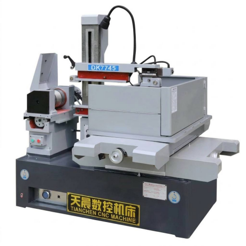
Wire EDM Machines: A Direct Answer to Common Buyer Questions
For workshops evaluating precision cutting equipment, the short answer is this: a wire EDM machine uses a continuously fed metal wire as an electrode to erode conductive material through controlled electrical discharges, allowing complex profiles, tight tolerances, and hard materials to be cut without direct mechanical contact. Buyers researching edm wire processing generally choose between three broad machine categories: medium-speed wire EDM, high-speed (reciprocating) wire EDM, and large-taper wire EDM, each suited to different combinations of thickness, taper angle, and surface finish requirements. An edm machine wire system is typically selected based on the part geometry, the material being cut, and the number of passes needed to reach a target finish, rather than on a single universal specification.
This article walks through the common types of wire EDM machines, how they are structured internally, where each type tends to fit best, how their relative performance compares across several criteria, and what ongoing maintenance typically involves. Practical selection guidance is included throughout, along with a comparison table and several data visualizations that summarize the relative positioning of each machine category.
- Wire EDM machining is a non-contact process that relies on spark erosion rather than cutting force
- Medium-speed wire EDM machines are widely used for general tool and die work
- High-speed (reciprocating) wire EDM machines are common where wire reuse and cost efficiency matter
- Large-taper wire EDM machines address parts requiring significant angled cutting
Choosing among wire EDM machine categories depends less on brand and more on matching machine capability to workpiece thickness, required taper angle, and finish tolerance for the parts actually being produced.
Common Types of Wire EDM Machines and Their Characteristics
Medium-Speed Wire EDM Machines
Medium-speed wire EDM machines, sometimes described as improved reciprocating traveling-wire machines, run the wire back and forth across the workpiece while applying multiple trim passes to progressively refine the cut surface. This category is often the default starting point for tool and die shops because it balances cutting speed, surface finish, and equipment cost reasonably well across a wide range of part geometries. Wire is typically molybdenum-based and is reused across multiple passes, which shops often view as a practical way to manage edm wire consumption without sacrificing finish quality on the final trim cut.
High-Speed (Reciprocating) Wire EDM Machines
High-speed wire EDM machines share the reciprocating wire-feed principle but are generally configured for faster rough-cutting throughput, often at the expense of surface finish compared to a heavily trimmed medium-speed setup. These machines tend to suit production environments where cycle time matters more than achieving the finest possible surface, and where subsequent finishing operations may already be part of the workflow. Because the wire travels back and forth, a single spool can be used across many parts, which is frequently cited as a practical cost consideration for high-volume rough cutting.
Large-Taper Wire EDM Machines
Large-taper wire EDM machines are built with wire guide heads and axis configurations capable of holding significant angles between the upper and lower wire guides, which allows the wire to cut steep draft angles into a workpiece in a single pass. This category is generally selected for parts such as stamping die components, extrusion dies, or other tooling where a pronounced taper or step profile is a functional requirement rather than a cosmetic one. Because the mechanical structure must maintain rigidity even as the wire guides swing to extreme angles, machine frame design and guide precision matter more here than in machines built primarily for straight-wall cutting.
| Machine category | Primary structural focus |
|---|---|
| Medium-speed wire EDM | Multi-pass trim accuracy and repeatable positioning |
| High-speed wire EDM | Wire feed reliability and rough-cutting throughput |
| Large-taper wire EDM | Wire guide rigidity across extreme angle ranges |
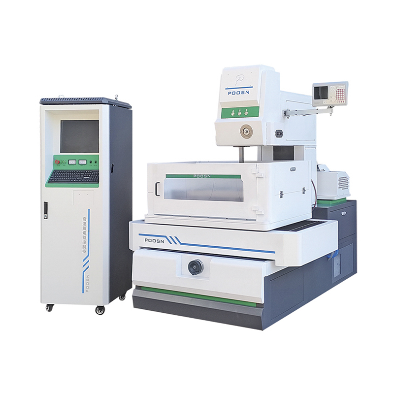
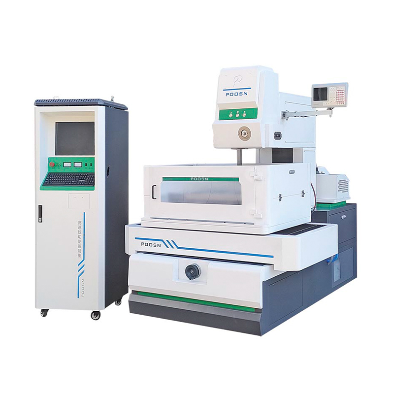
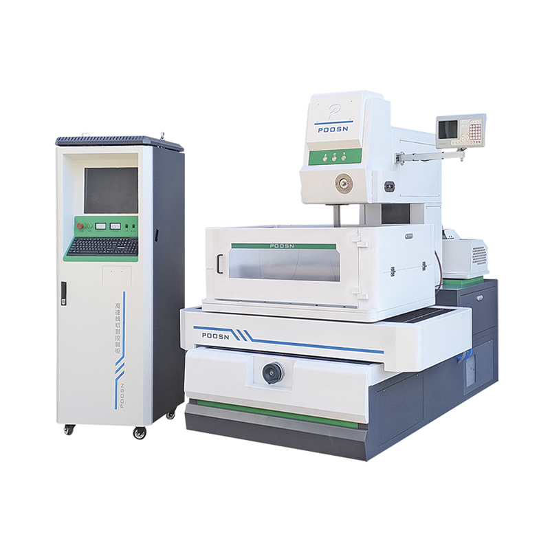
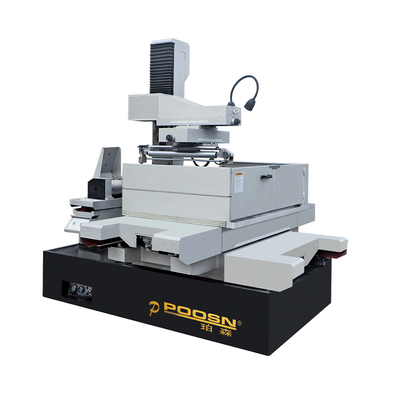
PS-C seriesMedium-speed wire EDM configuration for general tool and die applications |
DK77-BC seriesMedium-speed wire EDM configuration with extended trim-pass control |
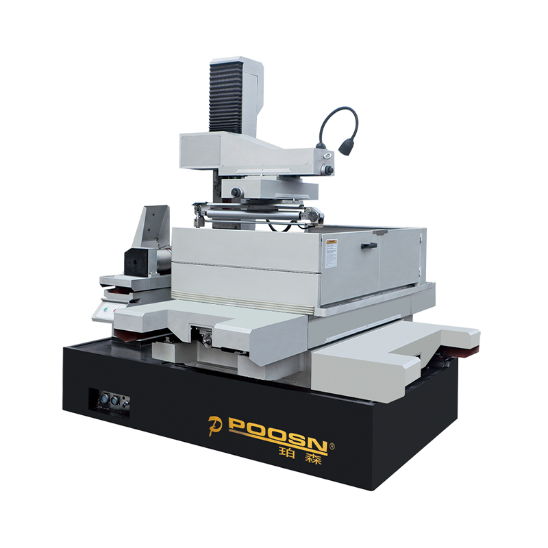
DK77-A seriesHigh-speed reciprocating wire EDM configuration |
DK77-B seriesHigh-speed reciprocating wire EDM configuration, alternate frame layout |
DK77-D seriesLarge-taper wire EDM configuration for steep-angle cutting |
The three categories are not strictly hierarchical; each is optimized for a different combination of speed, finish, and taper capability rather than one simply outperforming the others.
How Wire EDM Machines Work: Principles and Structure
A wire EDM machine removes material through a series of rapid electrical discharges between the wire electrode and the workpiece, both of which are submerged in or flushed with a dielectric fluid, usually deionized water. Each discharge vaporizes a tiny amount of material, and the dielectric fluid flushes away the resulting debris while also cooling the cut zone and helping to control the discharge gap. Because the wire never physically presses against the workpiece, cutting forces remain very low, which is part of why wire EDM is commonly used on hardened tool steels and other materials that are difficult to machine conventionally.
Positioning is handled by a CNC control system that drives the X-Y table (and, on taper-capable machines, the U-V wire guide axes) according to a programmed part profile, while a separate power supply unit governs the discharge parameters such as pulse frequency and current. The mechanical frame, wire transport system, and dielectric circulation system work together with the control electronics, so machine rigidity and control precision are generally considered together rather than as separate concerns when evaluating a machine.
Mechanical and structural system
|
Control and power system
|
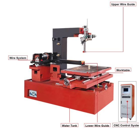
Because cutting force is minimal, wire EDM machine rigidity is mainly about maintaining positioning accuracy over time rather than resisting heavy mechanical loads.
Relative Cutting Speed Positioning Across Wire EDM Categories
Before comparing numbers, it helps to understand what "cutting speed" actually means in a wire EDM context. Actual cutting rate depends heavily on material type, workpiece thickness, wire diameter, and how many trim passes are programmed, so any single figure is only a rough guide rather than a fixed rating. The chart below presents a simplified, illustrative index rather than exact measured values, intended to show how the three machine categories generally compare to one another in typical rough-cutting scenarios. A higher index reflects a machine category that is generally associated with faster first-pass material removal under comparable conditions. These figures are for general orientation only and should not be treated as a guaranteed specification for any specific machine model.
Reading the chart, medium-speed wire EDM machines generally sit toward the higher end of this illustrative scale because multi-pass programming lets them combine a reasonably fast rough cut with additional trim cuts that recover surface finish afterward. High-speed reciprocating machines are positioned in the middle, reflecting their common role as workhorse machines for straightforward through-cutting where extreme finish is not the primary concern. Large-taper machines show a comparatively lower index on this particular chart, but that is not a weakness so much as a reflection of their design priority: their wire guide geometry and control system are optimized for maintaining accuracy at steep angles rather than for maximizing straight-cut throughput. In practice, a shop that primarily cuts tapered die components would not choose a machine based on this index alone, since taper capability would be the deciding factor rather than raw speed. It is also worth noting that within any one category, actual throughput varies with wire diameter, material conductivity, and how aggressively the pulse parameters are set. Thinner wire generally allows finer detail but can reduce the practical cutting rate, while thicker wire may cut faster but limits the smallest achievable internal corner radius. Workpiece thickness has a similar effect: cutting rate for a given machine typically declines as material thickness increases, because the dielectric fluid has to flush debris out of a longer discharge channel. Multi-pass strategies further complicate any single-number comparison, since a shop might deliberately slow down the first pass to protect wire life and rely on trim passes for finish, effectively trading raw speed for consistency. For buyers comparing machines side by side, request the vendor's own test-cut data for the specific material and thickness relevant to your parts rather than relying on generalized categories. Finally, keep in mind that machine condition, dielectric fluid quality, and wire feed consistency all influence real-world cutting rate as much as the underlying machine category does, so a well-maintained mid-tier machine can sometimes outperform a poorly maintained higher-spec one.
Application Scenarios and Key Selection Criteria for Wire EDM Machines
Wire EDM machines are used across tool and die manufacturing, mold making, aerospace component production, medical device manufacturing, and various automotive tooling applications, generally wherever a conductive material needs a precise profile cut without the mechanical stress of traditional machining. Selection typically comes down to matching machine capability to the specific part requirements rather than choosing a single "best" configuration for every job.
- Maximum workpiece thickness the machine can accommodate within its work envelope
- Maximum taper angle required, which determines whether a large-taper configuration is necessary
- Target surface finish and whether multiple trim passes are part of the intended process
- Material type and conductivity, since some materials require adjusted discharge parameters
- Expected production volume and whether wire consumption or cycle time is the bigger cost driver
- Compatibility with existing wire diameter and dielectric fluid systems already used in the shop
Tool and die shops that regularly cut stamping punches and blanking dies often prioritize taper capability and positioning repeatability, since these parts frequently combine straight walls with angled relief sections. Mold makers cutting core and cavity inserts tend to weigh surface finish heavily, because the wire-cut surface may be the final finish or may only require light polishing afterward. Aerospace and medical component producers frequently work with difficult alloys and tight dimensional tolerances, which places emphasis on control system stability and repeatable trim-pass performance rather than raw first-pass speed.
The most reliable way to select a wire EDM machine is to map your actual part thickness, taper, and finish requirements against a manufacturer's stated work envelope and taper range before comparing any other feature.
Surface Finish Improvement Across Successive Trim Cuts
One of the most practical concepts for anyone evaluating wire EDM machine wire processes is the relationship between the number of cutting passes and the resulting surface finish. A first, rough-cut pass generally removes bulk material quickly but leaves a comparatively coarse surface, since the discharge energy used for fast removal tends to leave larger recast marks. Subsequent trim passes use progressively lower discharge energy and tighter offsets, refining the surface with each pass. Shops commonly plan two to four total passes depending on the finish tolerance called out on the part drawing. The chart below illustrates this general relationship using a simplified relative roughness index rather than a specific Ra value tied to any one machine or material.
The steep drop between pass one and pass two on this chart reflects the general pattern in wire EDM: the largest single improvement in surface finish usually comes from adding just one trim pass after the initial rough cut. Each additional pass after that tends to deliver a smaller incremental improvement, which is why many shops stop at three or four passes once the diminishing returns outweigh the added cycle time. This trend is widely discussed in EDM process literature and reflects the underlying physics of discharge energy reduction rather than any single manufacturer's specific settings. A rough first pass typically uses higher current and longer pulse duration to maximize material removal rate, which inherently creates a deeper recast layer and coarser surface texture. Trim passes reduce current, shorten pulse duration, and often reduce the offset between the wire path and the finished profile, which is what allows the surface to be progressively refined without significantly changing the part's overall dimensions. For parts with a tight finish callout, four or more passes may be specified, while parts intended for further grinding or polishing might only require a single rough cut. It is also worth noting that pass count interacts with taper cutting: on large-taper machines, maintaining consistent finish across a steep angle can require additional passes compared to a straight-wall cut of similar thickness. Wire diameter and tension consistency also affect how predictably a machine converges toward a target finish across multiple passes, since any variation in wire position between passes can offset the intended finishing benefit. Shops that log actual measured Ra values per pass for their own machines and materials will get a far more accurate picture than any generalized chart, since actual finish depends on dielectric cleanliness, wire condition, and workpiece material as much as on pass count. Finally, buyers comparing wire EDM machine wire consumption should remember that more trim passes generally mean more wire used per part, so finish requirements and wire cost should be considered together during process planning.
Common Industry Sectors Utilizing Wire Cutting EDM Equipment
Wire EDM adoption varies meaningfully by industry, largely based on how often a given sector needs precise profiles cut into hard or difficult-to-machine conductive materials. Tool and die work remains one of the most common applications, since punches, dies, and related tooling frequently require both hardened materials and tight profile tolerances. Mold making follows closely, particularly for inserts with complex internal geometry that would be difficult to reach with conventional milling. Aerospace, medical device, and automotive tooling round out the remaining significant use cases, each with its own emphasis on material type, tolerance, and finish. The relative usage index below is illustrative, intended to convey general prevalence patterns commonly described in manufacturing industry sources rather than a precise market share figure.
Tool and die applications score highest on this illustrative index because hardened steel tooling components are a near-ideal match for wire EDM's strengths: the process handles hardened materials without the tool wear issues associated with conventional cutting, and it produces the sharp internal corners often needed in die sets. Mold making follows closely for similar reasons, particularly where an insert has fine internal detail that would otherwise require multiple conventional operations or specialized electrodes for sinker EDM. Aerospace and automotive sectors show comparable mid-range usage, generally tied to specific tooling and fixture components rather than being applied across every part in those industries. Medical device applications, while smaller in overall volume, often involve exacting tolerance requirements on small, intricate components, which is why wire EDM remains relevant there even at comparatively lower usage volume. It is worth noting that these five sectors are not mutually exclusive from a shop's perspective, since a single wire EDM machine in a job shop may serve tool and die customers one week and aerospace tooling customers the next. Sector prevalence also shifts over time as materials and part designs evolve, so a shop's actual customer mix is a more reliable guide to expected machine utilization than any generalized industry chart. Buyers evaluating a wire EDM machine wholesaler or supplier for a new purchase should weigh their own typical part mix more heavily than general industry statistics when specifying machine capability. For a job shop serving multiple sectors, versatility across thickness range and taper capability often matters more than being narrowly optimized for one industry's typical part profile. Because tool and die and mold making together represent a large share of common applications, many machine manufacturers naturally emphasize these use cases in their product design and configuration options. Even so, the underlying wire EDM process itself is largely material- and geometry-driven rather than industry-specific, meaning a well-configured machine can generally serve multiple sectors without requiring separate dedicated equipment for each one.
Detailed Comparison of Wire EDM Machine Categories
Comparing wire EDM machine categories across several criteria at once helps clarify why no single type is universally preferable. The radar chart below plots five commonly referenced criteria side by side for medium-speed, high-speed, and large-taper machines, using a simplified 0-10 relative index for each attribute. This kind of multi-criteria view is often more informative than any single spec sheet number, because it shows the trade-offs a shop accepts when choosing one category over another. As with the earlier charts, the values shown are illustrative and intended for general orientation, not a substitute for a specific machine's documented specifications. Reading the shape of each polygon rather than any single point tends to give the clearest picture of a machine category's overall profile.
Medium-speed High-speed Large-taper
The medium-speed polygon extends furthest along the cutting speed and surface finish axes, which is consistent with its role as a general-purpose machine that balances multi-pass finishing against reasonable throughput. The high-speed polygon shows its widest extension along maintenance simplicity, reflecting the comparatively straightforward reciprocating wire path that many shops find easier to service day to day. The large-taper polygon clearly extends furthest along the taper capability axis, which is exactly what this category is designed for, even though it shows a more modest reading on raw cutting speed. None of the three shapes dominates across all five axes, which visually reinforces the point that machine selection is a trade-off exercise rather than a search for a single best option. Shops that primarily need straight-wall cutting with strong surface finish will likely find the medium-speed profile most relevant to their needs. Shops focused on high-volume rough cutting where finish is handled downstream may lean toward the high-speed profile instead. Shops working with stamping dies, extrusion tooling, or other steeply angled components will generally find the large-taper profile's strength in that one axis more important than its comparatively average performance elsewhere. Rigidity scores are fairly close across all three categories in this illustration, which reflects the fact that wire EDM machines generally do not need to resist heavy cutting forces the way conventional milling machines do, so structural rigidity differences tend to show up more in long-term positioning accuracy than in obvious deflection during cutting. It is worth remembering that any specific machine model can vary from these generalized category profiles depending on its individual design choices, control system, and build quality. Buyers are encouraged to request test-cut samples or documented specifications from a wire EDM machine supplier for the particular model under consideration rather than relying solely on category-level comparisons like this one. Used together with the table below, this radar view is meant to support a more informed conversation with a manufacturer about which configuration best matches a shop's actual part mix.
| Criterion | Medium-speed | High-speed | Large-taper |
|---|---|---|---|
| Typical taper range | Moderate | Limited | Extended |
| Common finish strategy | Multiple trim passes | Single or light trim | Multiple trim passes |
| Typical wire handling | Reciprocating, reused | Reciprocating, reused | Reciprocating, reused |
| Best-suited part type | General profiles | High-volume rough cuts | Steep angle tooling |
No single wire EDM machine category wins on every criterion; the right choice depends on which one or two criteria matter most for your actual part mix.
Maintenance and Long-Term Upkeep of Wire EDM Equipment
Consistent maintenance is generally what separates a wire EDM machine that holds its accuracy for years from one that drifts out of tolerance prematurely. Because the process depends on a clean dielectric fluid path, stable wire tension, and precise wire guide positioning, routine attention to these systems tends to matter more than any single dramatic repair.
- Monitor dielectric fluid resistivity and replace filters on a regular schedule to maintain stable discharge conditions
- Inspect wire guides and diamond dies periodically, since wear here directly affects positioning accuracy
- Check wire tension calibration to keep cutting behavior consistent across passes
- Clean the wire feed path and power feed contacts to prevent inconsistent current delivery
- Verify axis positioning accuracy on a periodic basis, particularly after any significant relocation of the machine
- Keep the dielectric tank and flushing nozzles free of debris buildup to support stable flushing conditions
Shops that log dielectric fluid condition, filter replacement dates, and periodic accuracy checks tend to catch drift earlier, which generally reduces unplanned downtime compared to a purely reactive maintenance approach. Wire guide wear in particular is easy to overlook because its effects on part accuracy can be gradual rather than sudden, so a fixed inspection interval is often more reliable than waiting for a visible problem to appear.
Positioning accuracy on a wire EDM machine is maintained through routine dielectric, wire guide, and calibration checks rather than through any single one-time adjustment.
About POOSN – Professional Wire EDM Machine Manufacturer
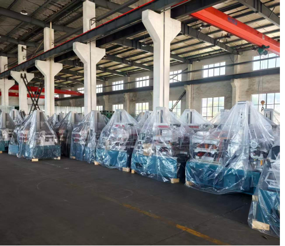
Taizhou Xinchengyang Machinery Manufacturing Co., Ltd. (POOSN) is a professional manufacturer specializing in the research, development and production of CNC Wire EDM machines. With more than 30 years of manufacturing experience, POOSN has developed extensive expertise in wire EDM technology and precision machining equipment.
Our product range covers different wire EDM solutions, including the PSC Series medium-speed Wire EDM machines, DK60BC medium-speed Wire EDM machines, and DK77 Series high-speed Wire EDM machines. We also provide customized machine configurations for different workpiece sizes, materials, thicknesses, taper requirements and production volumes.
POOSN operates a 13,703 m² manufacturing facility with a professional team of approximately 80 employees, including R&D engineers and quality control personnel. Our production process covers machining, machine assembly, electrical integration, testing and final inspection to help ensure stable machine performance before shipment.
We serve mold manufacturers, machining companies, distributors and industrial users in international markets, with OEM and ODM services available for specific customer requirements.
Whether you need a Wire EDM machine for precision mold manufacturing, general production, or specialized taper cutting, POOSN can recommend a suitable solution based on your application requirements.
Working with a manufacturer that covers medium-speed, high-speed, and large-taper wire EDM categories under one roof can simplify sourcing for shops that handle a mixed range of part geometries.
Frequently Asked Questions About Wire EDM Machines
Q1. What is a Wire EDM machine?A Wire EDM machine uses a continuously moving electrode wire and controlled electrical discharges to cut electrically conductive materials. It is widely used for molds, dies, precision tooling and components requiring complex profiles and high machining accuracy. |
Q2. How does a Wire EDM machine work?The machine guides a thin electrode wire through the workpiece while controlled electrical discharges remove material. Dielectric fluid cools the machining area and flushes away debris, while the CNC system controls the cutting path. |
Q3. What materials can a Wire EDM machine cut?Wire EDM can cut many electrically conductive materials, including tool steel, hardened steel, stainless steel, copper, brass, aluminum, carbide and other conductive alloys. Cutting performance depends on the material, thickness and machining parameters. |
Q4. What is the difference between Medium-Speed and High-Speed Wire EDM?Medium-Speed Wire EDM machines generally provide a balance of cutting efficiency, accuracy and surface finish, making them suitable for general machining and mold applications. High-Speed Wire EDM machines focus more on cutting efficiency and production productivity. |
Q5. How accurate is a Wire EDM machine?Machining accuracy depends on the machine structure, CNC system, wire tension, workpiece material, thickness and machining parameters. For applications requiring specific accuracy, customers should provide their workpiece drawing and requirements so the manufacturer can evaluate the suitable machine configuration. |
Q6. How long does molybdenum wire last?Molybdenum wire life depends on cutting speed, machining time, workpiece material, thickness, electrical parameters and wire tension. Regular inspection and proper maintenance can help maintain stable machining performance and extend wire service life. |
Q7. How do I choose the right Wire EDM machine?Consider the workpiece material, thickness, size, required accuracy, surface finish, taper angle and production volume. Providing these specifications to the manufacturer is the best way to select a suitable machine model and configuration. |
Q8. How do I choose a reliable Wire EDM manufacturer?Consider the manufacturer's manufacturing experience, machine quality, production capability, quality control, technical support, spare parts availability and after-sales service. A reliable manufacturer should also be able to recommend a machine based on your actual application requirements. |
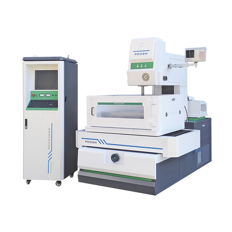
-
Phone
+86-0523-86268788 +86-13815960366 +86-13912191163Email
[email protected]Address
No. 366, Yusheng Road Jiulong Town, Hailing District Taizhou City, China
Copyright © Taizhou Xinchengyang Machinery Manufacturing Co., Ltd. All Rights Reserved.
Custom edm machine for sale
wholesale edm machine manufacturers
