

 English
 русский
 عربى


Industry News
Home / News / Industry News / Wire EDM for Medical Components: Tolerances, Materials and Machine Choice
Wire EDM for Medical Components: Tolerances, Materials and Machine Choice
2026-10-20
A 0.25 mm cannula wall, a biopsy punch that must shear cleanly on the first pass, and a spinal plate whose screw holes follow a converging trajectory: three very different parts, one shared manufacturing route. Wire EDM for medical components is usually the process engineers reach for when the part is conductive, thin-walled or already hardened, and when a burr or a grinding mark would turn a lot into scrap.
The short answer up front: a properly maintained wire EDM holds ±0.005 mm as a routine production tolerance, reaches ±0.002 mm with multiple trim passes, and cuts hardened titanium or cobalt-chrome without applying cutting force to the workpiece. It also has a hard boundary. The process only cuts electrically conductive materials, so PEEK, zirconia, alumina and PMMA bodies stay on milling, turning or molding routes. Knowing exactly where the process wins, and where it stops, is what keeps a medical supply chain stable instead of stuck in a rework loop.
What follows is a practical view of the process: how the cut works, which tolerances are realistic, which component families belong on the machine, how the medium speed and high speed series differ, and what to put on a drawing before you request a quote.
Content
- 1 Why Wire EDM for Medical Components Is Specified
- 2 How the Cut Works: Kerf, Trim Passes and Wire Choice
- 3 Wire EDM for Medical Components: Tolerance and Finish Benchmarks
- 4 Component Families and the Feature That Drives the Process
- 5 Matching the Machine Series to Medical Work
- 6 Material Behaviour: Where the Process Earns Its Keep
- 7 Surface Integrity, Cleanliness and Validation
- 8 Cost, Lead Time and the Buy-or-Outsource Question
- 9 Maintenance Routine That Protects Accuracy
- 10 Specification Checklist Before You Request a Quote
- 11 Frequently Asked Questions About Wire EDM for Medical Components
- 11.1 Can wire EDM cut titanium medical implants?
- 11.2 Does wire EDM produce burr-free surgical instrument parts?
- 11.3 Is wire EDM suitable for a final implant surface?
- 11.4 What tolerance should I specify on a medical wire EDM part?
- 11.5 High speed or medium speed, which is better for medical work?
- 11.6 Can wire EDM cut PEEK, zirconia or ceramic components?
- 11.7 What does a supplier need to quote a medical wire EDM job?
- 12 Putting the Route Together
Why Wire EDM for Medical Components Is Specified
Medical parts rarely fail because a shop cannot hit a nominal dimension once. They fail because the tenth part behaves differently from the first, because a deburring step scratched a sealing face, or because a heat-treated blank moved after the last operation. Wire EDM addresses those three risks directly.
No cutting force means thin walls survive
The electrode never touches the workpiece. Material is removed by controlled electrical discharges in a dielectric, so there is no tool pressure, no cutter deflection and no clamping load transferred into a 0.2 mm wall. That single characteristic is why a wire cut EDM machine handles cannula features, leaflet flexures and thin implant windows that a milling cutter would push out of tolerance.
Full hardness, no softening, no tool wear
Ti-6Al-4V, 17-4PH at H900, cobalt-chrome, MP35N and tungsten carbide are all cut at their finished hardness. There is no annealing step before machining and no re-hardening afterwards, which removes a whole sequence of distortion risk from the routing. Tool wear also disappears from the equation, because the wire is consumed and replaced continuously, so the hundredth part is cut with the same geometry as the first.
Edges that do not need a deburring operation
A sheared or milled edge leaves a burr that must be removed by hand, tumbling or electropolishing. Each of those steps adds handling, inspection and the risk of rounding a critical corner. Wire EDM produces an edge defined by the spark, so burrs are absent by construction. For components that contact tissue, that is both a quality and a validation advantage.
Wire EDM removes the constraints of hardness, wall thickness and burr generation at the same time, leaving conductivity, fixturing and cut time as the real limits.
How the Cut Works: Kerf, Trim Passes and Wire Choice
Understanding the mechanics makes drawing review much faster, because most manufacturability comments on a medical print come back to three numbers: wire diameter, kerf and the number of trim passes.
Kerf defines the smallest feature you can draw
The kerf equals the wire diameter plus twice the spark gap. A common 0.25 mm brass wire produces a kerf around 0.30 mm to 0.33 mm depending on the energy setting, while micro wire in the 0.02 mm to 0.05 mm range opens up slots and radii that would otherwise be impossible. Internal corners always carry a radius of at least half the kerf, so a design that calls for a sharp internal corner will be produced with a small radius whether the drawing shows it or not. Putting a 0.15 mm to 0.20 mm corner radius on the print avoids a revision later.
Rough cut plus skim cuts
A single rough pass removes material quickly and leaves a recast layer in the range of a few micrometres, with a surface finish near Ra 1.6 µm. Each subsequent skim pass removes a thin shell, typically 5 µm to 30 µm, and progressively improves both geometry and surface. Two skims bring most medical work to Ra 0.4 µm, and three or four skims can push toward Ra 0.1 µm to 0.2 µm with a recast layer under 1 µm to 2 µm. The trade-off is time: a multi cut wire EDM cycle can run 40 to 80 percent longer than a rough cut alone, so trim passes should be attached to functional surfaces rather than applied to the entire profile.
Wire and dielectric decisions
Brass wire is the general-purpose choice, zinc-coated brass improves flushing and speed on thick sections, and molybdenum wire is used on reciprocating high speed WEDM machines where the same wire runs repeatedly. On titanium and cobalt-chrome, wire selection also touches cleanliness: copper and zinc from the wire can transfer onto the cut surface, so functional faces are usually given a final skim, an ultrasonic clean and a passivation or electropolish step. The dielectric is deionized water, and its resistivity must be held inside the machine builder's band. Drifting outside that band changes the spark gap, which changes the pitch of a hole pattern that was previously running well.
Wire diameter sets the kerf and the minimum corner radius; trim passes set the finish and the cost. Both belong on the drawing, not in a verbal agreement.
Wire EDM for Medical Components: Tolerance and Finish Benchmarks
Tolerance claims are meaningless without naming the process variant behind them. On a medical part, the number that matters is the one that repeats across a production lot, not the one achieved once in a demonstration. The chart below compares the tolerance band a well-maintained machine can hold in normal production, not the best single-part result. The values assume a controlled shop floor, a thermally settled machine and a fixture that does not push back against the cut. Use it to sanity-check a drawing before sending an RFQ, and to decide how many trim passes a given feature genuinely needs.
Typical production tolerance band, five metal-cutting routes
- Wire EDM, rough plus two skims ±0.002 mm
- Wire EDM, rough pass only ±0.005 mm
- CNC milling, production run ±0.010 mm
- Fiber laser, small features ±0.015 mm
- Stamping and blanking ±0.020 mm
The jump from a rough pass to a two-skim cycle is roughly a factor of two and a half in tolerance, and it comes with a real time cost rather than a change in machine capability. A single rough cut at ±0.005 mm is genuinely sufficient for stamping punches, fixture plates and rough tooling blanks, which is why high speed machines remain heavily used in medical tool rooms. Adding skims narrows the band and improves surface finish at the same time, so the decision is usually driven by whether the surface is functional or merely structural.
The comparison with milling is often misunderstood. Milling can hold ±0.010 mm on a rigid part, but a 0.3 mm rib will deflect under cutter pressure and the tolerance drifts with tool wear across a batch. Wire EDM does not deflect and does not wear a tool, so its advantage is less about the number and more about the repeatability of that number from the first part to the five-hundredth. For long medical production runs, that consistency is worth more than a tighter nominal figure.
Laser cutting sits at a wider band and adds a heat-affected zone plus a recast layer that must be removed on implant surfaces, which is why it dominates stent and tube work where speed matters but generally loses to wire EDM on thick, hard or burr-sensitive sections. Stamping is fast and cheap at volume but introduces burrs and tool wear, and the tolerance drifts as the die wears. None of these processes is universally better; they simply fail in different ways, and the medical drawing should be written with the intended process in mind.
Two practical conclusions follow. First, do not call ±0.002 mm on every dimension of a component, because each tightly toleranced feature forces extra trim passes across the whole profile and multiplies cycle time. Second, when a drawing does specify a tight band, ask the supplier for a process capability figure rather than a machine specification. A Cpk of 1.33 on the critical dimension, measured across at least thirty consecutive parts, tells you far more than a brochure number about what the equipment can do in a real shop.
Reserve the ±0.002 mm callouts for functional features only, and verify them with a capability study instead of a single first-article measurement.
Component Families and the Feature That Drives the Process
Medical work on a wire EDM machine clusters into a handful of families. Each one usually has a single feature that decides the machine, the wire and the number of passes.
| Component family | Common material | What the process contributes | Control point |
|---|---|---|---|
| Surgical forceps, needle holders, scissor blanks | 420 and 440 stainless, titanium | Box joints, angled slots, jaw profiles in one setup | Edge burr and taper on angled faces |
| Biopsy punches, cannula, needle features | 304 and 316LVM stainless, Nitinol | Thin walls, sharp bevels, side slots without distortion | Wall collapse and internal burr |
| Bone plates, spinal components, implant windows | Ti-6Al-4V, cobalt-chrome | Hole patterns, contours and windows after hardening | Recast layer and surface chemistry |
| Orthopedic guides, reamers, rasps | 17-4PH at H900, tool steel | Flutes, keyways and guide slots at full hardness | Hardness range and wear resistance |
| Dental files and abutment features | Stainless, titanium | Fine profiles and narrow slots with micro wire | Wire diameter against feature size |
| Mold inserts for microfluidic and lab-on-chip parts | Hardened tool steel, carbide | Deep ribs and sharp internal corners with controlled taper | Corner radius and taper accuracy |
| Punches, dies and fixtures for medical stamping | D2, carbide, hardened stainless | Punch and die clearances with a single wire setting | Clearance consistency across the die |
The last two rows deserve attention because they are easy to overlook in a medical bill of materials. Wire EDM for mold making and wire EDM for tooling often decide whether the downstream stamping or molding cell can hold its own tolerance, and a die insert that is cut with a wandering taper will produce a burr on every part it makes. Investing in taper control at the tooling stage usually pays back faster than adding a deburring operator at the end of the line.
Identify the one feature that decides the process for each family, and write the tolerance and surface requirement around that feature rather than around the whole part.
Matching the Machine Series to Medical Work
Medical work does not sit on one machine. A tool room cutting stamping punches, a cell producing implant windows and a job shop cutting 60 degree angled slots in forceps all need different priorities, and the practical split in most Chinese wire EDM factories follows the same three bands.
Medium speed band: precision and finish
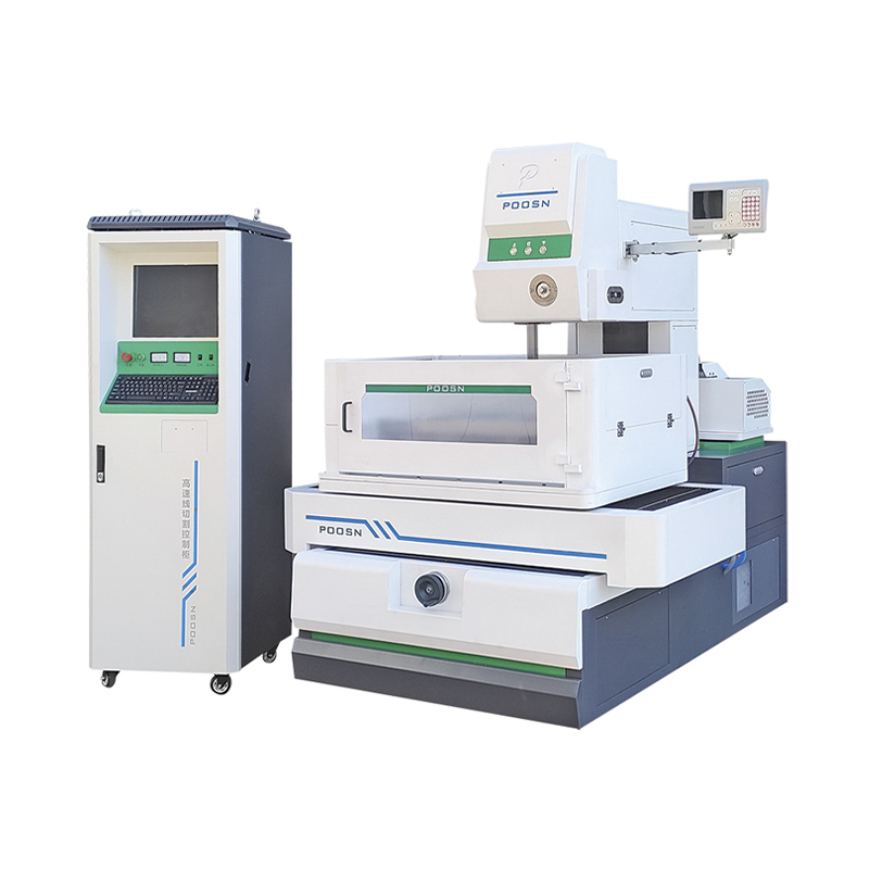
The PS-C series, covering PS35C, PS45C, PS50C and PS60C, is the natural fit for implant features, punch and die details and any part where the drawing carries a ±0.005 mm callout plus a fine surface requirement. These are multi cut machines with servo control, and the PS35C in particular is widely used where a compact work envelope and high accuracy matter more than raw cutting speed.
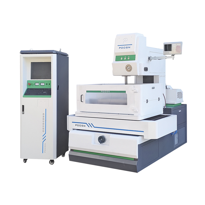 PS35C Precision Medium-Speed Wire Cut EDM MachineA compact multi-cut, servo-controlled medium-speed WEDM for ±0.005 mm work and fine surfaces, balancing precision with cost-performance.View Product →
High speed band: cost and throughput
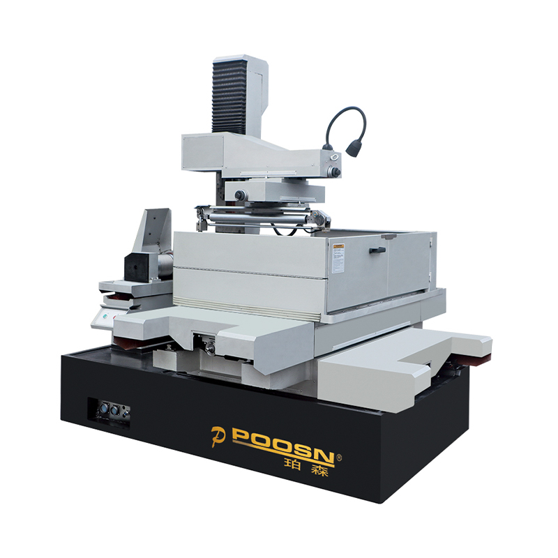
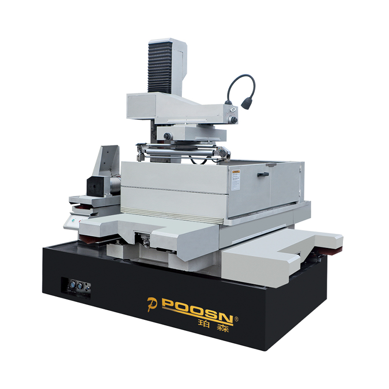
The DK77 series, from DK7725 through DK7735, DK7745 and DK7745F, uses reciprocating molybdenum wire and delivers the lowest running cost per hour. For fixture plates, tooling blanks, prototype brackets and parts where ±0.01 mm is acceptable, a high speed WEDM is often the most economical route, and it remains the workhorse of medical tool rooms that support their own stamping or molding operations.
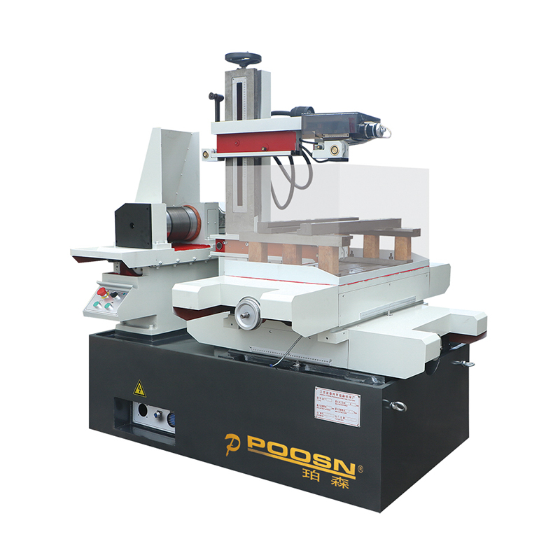 DK-7745 CNC High-Speed Wire Cut EDM MachineA 4-axis high-speed WEDM with 400 × 600 mm travel and reciprocating wire, suited to cost-conscious complex shapes and larger workpieces.View Product →
Large taper band: angled features in one pass
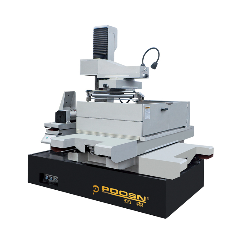
Surgical instruments frequently carry angled slots, draft faces and relief angles that would otherwise need a second operation. The DKD series, including the DK45D, DK55D, DK63D and DK80D, is built around 30 degree and 60 degree taper capability, which allows a large taper wire EDM to cut a converging slot or a drafted wall in a single setup and hold the angle along the full height of the part.
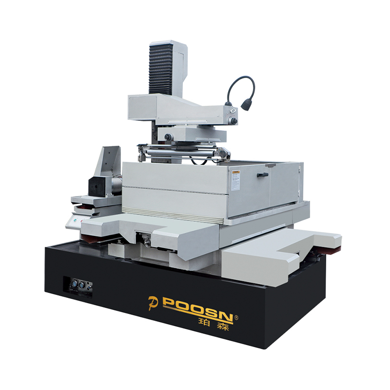 DK45D CNC Large Taper Wire Cut EDM MachineA large-taper WEDM with ±30° cutting and X8 AUTOCUT control, suited to complex molds and angled features up to 450 mm thick.View Product →
For buyers sourcing from a China wire EDM manufacturer, the practical question is not which series is best but which combination covers the product mix. A supplier that builds medium speed, high speed and taper platforms in the same factory can quote the whole medical range without subcontracting the awkward parts, and that matters when a project moves from prototype to production. Custom fixture design, voltage requirements, wire diameter ranges and control language should all be settled at the specification stage rather than after the purchase order.
Choose the series by the tightest functional feature in your product mix, then add the cheaper platform for the parts that do not need it.
Material Behaviour: Where the Process Earns Its Keep
Every conductive medical material can be cut, but they do not behave the same way. The differences show up in cutting speed, in the recast layer and in how much post-processing the part needs.
| Material | Behaviour on the machine | Typical adjustment |
|---|---|---|
| Ti-6Al-4V | Cuts steadily, but the surface can pick up copper or zinc from the wire | Final skim, ultrasonic clean, passivation or electropolish |
| 316LVM stainless | Predictable and fast, low recast thickness | Standard multi cut cycle with two skims |
| Cobalt-chrome and MP35N | Hard and wear resistant, slower erosion, higher wire consumption | Reduced energy on finish passes to limit microcracking |
| Nitinol | Heat input can shift the transformation temperature | Low-energy trim passes and a documented thermal history |
| 17-4PH at H900 | Cut at full hardness without distortion | Rough and two skims, check for retained stress on thin sections |
| Tungsten carbide | Very slow, high wire wear, edge chipping risk | Lower discharge energy, dedicated carbide settings |
| Inconel 718 | Stable but slow, recast layer tends to be thicker | Extra skim pass and a hardness check after cutting |
Two boundary conditions matter as much as the table. Non-conductive materials simply cannot be cut by this process, so a specification that calls for wire EDM on a zirconia implant or a PEEK cage is a drawing error, not a supplier problem. Magnetic and low-conductivity alloys, by contrast, cut fine but may need a different wire and a slower servo response to avoid wire breakage in deep, narrow sections.
Wire EDM for titanium and wire EDM for carbide are the two searches most often followed by a question about surface quality, and both come down to the same principle: the final trim pass defines the surface that the patient or the assembly will actually see. If the last cut is a rough pass, the recast layer and the transferred wire elements are part of the finished product whether the drawing mentions them or not.
The material determines the cutting parameters, but the final trim pass determines the surface chemistry of the delivered part.
Surface Integrity, Cleanliness and Validation
The recast layer is a thin, rapidly solidified skin that differs in structure from the base metal. On a structural bracket it is irrelevant. On an implant or a tissue-contacting edge it becomes a documented characteristic, because a cracked or porous recast layer can trap residue and become a fatigue initiation site. Skim passes reduce that layer to 1 µm to 2 µm in most medical work, and a subsequent electropolish removes the remainder while smoothing the surface further.
Cleaning is a process step, not a wipe-down. A typical sequence runs from a deionized water rinse and ultrasonic bath to a passivation step such as ASTM F86 for stainless components, followed by a controlled drying stage. Each step needs a record if the part is going into an ISO 13485 quality system, and the records should link back to the wire lot, the dielectric condition and the operator.
Validation expectations differ by customer but follow a familiar shape. Equipment qualification covers installation, operation and performance. Process validation covers the parameter window: wire type, tension, flush pressure, water resistivity, offset and number of passes. First-article inspection confirms the geometry against the drawing, and ongoing capability monitoring confirms that the process has not drifted. A supplier who can present a parameter sheet and a capability study alongside the part is far easier to qualify than one who can only present a certificate of conformance.
Traceability also deserves a mention in the purchasing conversation. For medical work, the wire grade, the dielectric resistivity log and the machine maintenance record are often as important as the inspection report, because they explain why the surface met spec instead of merely confirming that it did.
A medical wire EDM process is defined by its parameter window and its records, not by the machine model on the floor.
Cost, Lead Time and the Buy-or-Outsource Question
Price differences between quotes for the same medical part are usually not a machine-quality issue. They come from the assumptions each supplier makes about passes, fixtures and inspection. The drivers below explain most of the spread.
- Part envelope and fixture complexity. A part that needs a dedicated vacuum or adhesive fixture carries cost before the first spark.
- Number of trim passes. Every skim adds cycle time and wire consumption, and four passes can nearly double a rough-cut cycle.
- Count of tight-tolerance callouts. Ten ±0.002 mm dimensions cost far more than one, because the whole profile inherits the extra passes.
- Material. Carbide and cobalt-chrome erode slowly and consume more wire than stainless.
- Start holes and wire threading. Deep or numerous start holes add setup time, especially on parts that cannot be re-threaded automatically.
- Documentation. Validation packages, material certificates and inspection reports are real engineering hours.
On the sourcing side, buying direct from a wire EDM factory usually shifts the cost structure most on repeat work, where the fixture is amortized and the parameter set is proven. For a one-off prototype, paying a supplier to absorb the setup is often the cheaper decision even at a higher hourly rate. When volumes justify a machine, price comparisons should be made on the delivered cost per part at the required number of passes, not on headline equipment figures.
Wholesale and OEM arrangements follow the same logic. A customized wire cutting EDM machine built around a specific product family, with a fixed work envelope and a preset parameter library, often produces better economics than a general-purpose machine used at a fraction of its capability.
Compare quotes on cost per compliant part at a defined number of passes, and the apparent price gap usually explains itself.
Maintenance Routine That Protects Accuracy
Most accuracy complaints traced back to a wire EDM turn out to be maintenance issues rather than mechanical failure. A short, disciplined routine prevents the majority of them.
| Interval | Check | Why it matters |
|---|---|---|
| Daily | Water resistivity, filter pressure, wire tension, guide condition | Resistivity drift changes the spark gap and therefore the pitch |
| Weekly | Fixture alignment, table cleanliness, nozzle and flush paths | Poor flushing causes wire break and taper error |
| Monthly | Backlash, squareness, leveling, resin condition | Small geometry errors accumulate into out-of-tolerance parts |
| Quarterly | Ball screw lubrication, calibration verification, generator check | Positioning accuracy and surface consistency depend on both |
| Annual | Full geometric survey against the acceptance record | Establishes a baseline for the next year's validation |
The single most common mistake is treating the dielectric as a consumable detail. Water quality affects the spark gap, the surface finish and the corrosion behaviour of the part, and a resistivity log takes less than a minute per shift to maintain. Shops that keep that log almost never see the slow, unexplained pitch drift that costs a week of investigation.
Log dielectric resistivity every shift: it is the cheapest early warning system on a precision wire EDM.
Specification Checklist Before You Request a Quote
A well-prepared RFQ shortens the evaluation cycle and removes most of the assumptions that cause disputes later.
- State the material and its condition, including hardness and any prior heat treatment.
- Mark which dimensions are functional and which are reference, rather than tolerancing everything equally.
- Provide the minimum internal corner radius allowed, or ask the supplier to add one.
- Specify the surface finish and recast requirement on functional faces only.
- Identify where start holes may be placed and whether they can be drilled or must be EDM drilled.
- Describe the fixture interface, including any features that must remain untouched by clamping.
- State the inspection method, the sampling plan and the documentation package required.
- Confirm the annual volume and the expected ramp, so the supplier can quote the right number of passes.
A drawing prepared this way typically comes back with a realistic process route, a defensible price and a cycle time that will still hold when the order moves into production.
Every assumption left out of the RFQ becomes a change order later, so spend the extra hour on the drawing before sending it.
Frequently Asked Questions About Wire EDM for Medical Components
Can wire EDM cut titanium medical implants?Yes. Ti-6Al-4V and commercially pure titanium are both conductive and cut cleanly at full hardness. The caution is on surface chemistry rather than machinability: the final trim pass, cleaning sequence and passivation or electropolish step should be specified, because titanium can pick up copper or zinc from the wire if the functional face is left on a rough cut. |
Does wire EDM produce burr-free surgical instrument parts?Burrs are absent by the nature of the process, since material is eroded rather than sheared. Very thin sections can still show a fine edge or a slight recast lip, which a skim pass or a short electropolish removes. For jaws, box joints and angled slots, this is why the process is often preferred over milling followed by hand deburring. |
Is wire EDM suitable for a final implant surface?It can be, provided the surface is finished with trim passes and followed by an appropriate cleaning and polishing sequence. Many implant programs use wire EDM for the contour or the window and then rely on electropolishing for the final surface. The drawing should state which surfaces are finished by EDM and which are finished downstream. |
What tolerance should I specify on a medical wire EDM part?For most production work, ±0.005 mm is achievable with a rough pass and one or two skims. Reserve ±0.002 mm for functional features that genuinely need it, such as mating bores or sealing faces. Tolerancing every dimension tightly raises the part cost without improving function. |
High speed or medium speed, which is better for medical work?Medium speed platforms such as the PS-C series are the usual choice for implants, fine punches and parts with tight pitch requirements. High speed machines such as the DK77 series remain economic for fixtures, tooling blanks and less critical features, and many factories run both so that each job goes to the appropriate platform. |
Can wire EDM cut PEEK, zirconia or ceramic components?No. These materials are not electrically conductive, so the process cannot erode them. They belong on milling, turning, grinding or molding routes. Confirming conductivity before writing a process specification avoids a drawing that no EDM supplier can quote. |
What does a supplier need to quote a medical wire EDM job?A 3D model or drawing with tolerances marked as functional or reference, the material and heat treatment, the required surface finish, the annual volume and the inspection and documentation requirements. Supplying those five items usually produces a quote that survives contact with production. |
Putting the Route Together
Wire EDM for medical components works best when it is treated as a defined process rather than a fallback. Decide which feature drives the tolerance, choose the machine band that matches it, write the trim passes and the cleaning sequence into the specification, and ask for capability data rather than a machine rating. That approach keeps the first article and the thousandth part in the same tolerance band, which is the only definition of precision that matters in medical manufacturing.
| Comparing platforms medium speed wire cut EDM machine series covers the PS-C range used for implant and punch work. |
Material guidance special material processing solutions explains how hard and exotic alloys are handled in production. |
Precision in medical wire EDM is a documented process window, not a machine badge.
-
Phone
+86-0523-86268788 +86-13815960366 +86-13912191163Email
[email protected]Address
No. 366, Yusheng Road Jiulong Town, Hailing District Taizhou City, China
Copyright © Taizhou Xinchengyang Machinery Manufacturing Co., Ltd. All Rights Reserved.
Custom edm machine for sale
wholesale edm machine manufacturers
